ESE 345
Computer Architecture Project
Pipelined SIMD multimedia unit design with the
VHDL/Verilog hardware description language
1
Introduction
Purpose: To learn a use of VHDL/Verilog hardware
description language and modern CAD tools
for the structural and behavioral design of a four-stage pipelined multimedia
unit with a reduced set of multimedia instructions similar to those in the Sony Cell SPU and Intel SSE architectures.
CAD
Tools:
Mentor Graphics Modelsim at the Undergraduate CAD Lab
(room 281 Light Eng. Bldg.) or any other VHDL/Verilog simulator (e.g. Aldec, Vivado).
It is a one/two-students project.
2
Procedure
1.
It is suggested to
read Chapter 3.6-3.8 on subword parallelism to understand the concept
of multimedia processing
introduced as the MMX architecture for Intel processors in the 1990s.
2.
Refresh your knowledge of VHDL/Verilog in the HDL
design of digital
circuits by reading
Chapter 4.14
(Verilog)
and this VHDL
tutorial.
3.
Part 1.
Develop and submit behavioral HDL code and its
verification results for all
multimedia ALU operations at the 3rd stage. (No
knowledge of pipelining & forwarding is expected/used at that step.
4.
Develop
the
HDL model
of the
four-stage multimedia unit
and its modules. As an example,
look how the
Verilog code is used to describe the operation of the 5-stage MIPS pipeline.
5.
Verify individual modules
of your design with their testbenches before instantiating them in higher order
modules. Verify the final model with
a testbench module and generate file Results
showing the status of each stage of the unit during execution.
3
Requirements
The complete
4-stage pipelined design
is to be developed in a structural/RTL manner with several modules operating simultaneously.
Each module represents a pipelined stage with its interstage register. The major units inside those stages
modules are described below.
1.
Multimedia ALU
Takes up to three inputs
from the Register
File, and calculates the result based
on the current instruction to be performed.
The ALU must be implemented as behavioral model in VHDL or continuous assignment (dataflow models in
Verilog).
2.
Register File
The register file has 32 128-bit
registers. On any cycle, there can be 3 reads and 1 write. When executing
instructions, each cycle two/three 128-bit register values are read, and one 128-bit result can be written if a write signal is valid. This
register write signal must be explicitly declared so it can be checked
during simulation and demonstration of your design. The register module must be implemented as a behavioral model in VHDL (dataflow/RTL model in Verilog).
3.
Instruction Buffer
The
instruction buffer can store 64 25-bit instructions. The contents of the buffer
should be loaded by the testbench
instructions from a test file at the start of simulation. On each cycle, the instruction specified by the Program Counter (PC) is fetched,
and the value of PC is incremented by 1.
The
Instruction Buffer module must be implemented as a
behavioral model in VHDL (dataflow/RTL model in Verilog).
4.
Forwarding Unit
Every
instruction must use the most recent value of a register, even if
this value has not yet been written
to the Register File. Be mindful of the ordering of instructions; the most
recent value should be used,
in the event of
two consecutive writes to a register, followed by a read from that same register. Your processor should never stall in the event of
hazards.
 Take extra care
of which instructions require forwarding, and which ones do not. Namely, NOP and the instructions with
Immediate fields do not contain one/two register sources. Only valid data
and source/destination registers should be considered
for forwarding.
Take extra care
of which instructions require forwarding, and which ones do not. Namely, NOP and the instructions with
Immediate fields do not contain one/two register sources. Only valid data
and source/destination registers should be considered
for forwarding.
5.
Four-Stage Pipelined Multimedia Unit
Clock edge-sensitive pipeline
registers separate the IF, ID, EXE, and WB stages. Data should be written to
the Register File after the WB Stage.
All
instructions (including li)
take four cycles to complete. This pipeline
must be implemented as a structural model with modules for each
corresponding pipeline stages and their
interstage registers. Four instructions can be at different
stages of the pipeline at every cycle.
6.
Testbench This
module loads the instruction buffer using data loaded from a file, begins
simulation, and upon completion, compares the
contents of the register file to a file containing the expected results.
This expected results
file does not need to be auto-generated. Instead, this can be manually entered when designing a test program.
This must be
implemented as a behavioral model.
7.
Assembler This is a separate
program written in any language your team prefers
(i.e. Java, C++, Python). Its purpose is to convert an assembly file to
the binary format for the Instruction Buffer. This assembler does not need to be robust, and can
assume very specific syntax rules
that you as a team decide.
8.
Results File This file must show the status
of the pipeline for each cycle during program execution. It should include the
opcodes, input operand, and results of the execution of instructions, as well
as all relevant control signals and
forwarding information. This should be carried
out by your testbench.
4
Instruction
Formats and Opcode Description
4.1
Load Immediate
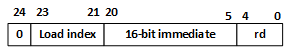
li: Load a 16-bit Immediate
value from the [20:5] instruction field into the 16-bit field specified by the
Load Index field [23:21] of the 128-bit register rd. Other fields of register rd are not changed.
Note that a LI instruction first reads register rd and then (after
inserting an immediate value into one of its fields) writes it back to register
rd, i.e., register rd is both a source and
destination register of the LI instruction!
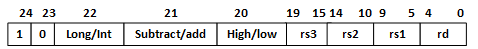
4.2
Multiply-Add
and Multiply-Subtract R4-Instruction Format
Signed operations are performed with
saturated rounding that
takes the result,
and sets a floor and ceiling corresponding to the
max range for
that data size.
This means that
instead of over/underflow wrapping, the max/min values are used.
|
Size
(Num Bits)
|
Min
|
Max
|
|
Long
(64)
|
-263
|
+263 − 1
|
|
Int
(32)
|
-231
|
+231 − 1
|
The tables below show the
description for each operation:
|
LI/SA/HL
[22:20]
|
Description
of Instruction Code
|
|
000
|
Signed
Integer Multiply-Add Low with Saturation: Multiply low 16-bit-fields of each 32-bit field of
registers rs3 and rs2, then add 32-bit products to
32-bit fields of
register rs1,
and save result in register rd
|
|
001
|
Signed
Integer Multiply-Add High with Saturation: Multiply high 16-bit-fields of each 32-bit field
of registers rs3 and rs2, then add 32-bit products to
32-bit fields of
register rs1,
and save result in register rd
|
|
010
|
Signed Integer
Multiply-Subtract Low with Saturation: Multiply low 16-bit-fields of each 32-bit field of registers rs3 and
rs2, then subtract 32-bit products from 32-bit
fields of register rs1, and save result in register rd
|
|
011
|
Signed
Integer Multiply-Subtract High with Saturation: Multiply high 16-bit- fields of
each 32-bit field of registers rs3 and
rs2, then subtract 32-bit products
from
32-bit fields of register rs1, and save result in register rd
|
|
100
|
Signed
Long Integer Multiply-Add Low with
Saturation:
Multiply low 32-bit- fields of each
64-bit field of registers rs3 and
rs2, then add 64-bit
products to 64-bit
fields
of register rs1,
and save result in register rd
|
|
101
|
Signed Long Integer
Multiply-Add High with Saturation:
Multiply high 32-bit- fields of each
64-bit field of registers rs3 and
rs2, then add 64-bit
products to 64-bit
fields
of register rs1,
and save result in register rd
|
|
110
|
Signed
Long Integer Multiply-Subtract Low with
Saturation:
Multiply low 32- bit-fields of each 64-bit field
of registers rs3 and
rs2, then subtract 64-bit
products from
64-bit fields of register rs1, and save result in register rd
|
|
111
|
Signed Long
Integer Multiply-Subtract High
with Saturation: Multiply high 32- bit-fields of each 64-bit
field of registers rs3 and
rs2, then subtract 64-bit
products from
64-bit fields of register rs1, and save result in register rd
|
4.3
R3-Instruction Format
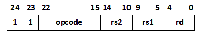
In
the table below,
16-bit signed integer
add (AHS), and subtract
(SFHS)
operations are performed with saturation to signed halfword rounding that takes a 16-bit signed
integer X, and converts it to -32768 (the most negative 16-bit signed value) if
it is less than -32768, to +32767 (the highest positive 16-bit signed value) if
it is greater than 32767, and leaves it unchanged otherwise.
|
Opcode
[22:15]
|
Description of Instruction Opcode
|
|
xxxx0000
|
NOP:
no operation.
Make sure that a NOP instruction does not write anything to the register file!
|
|
xxxx0001
|
SHRHI:
shift right halfword
immediate: packed 16-bit halfword shift right
logical of the contents of register rs1 by the value of the 4 least significatn
bits
of instruction field
rs2 . Each
of the results is placed into
the corresponding 16-bit
slot in register rd . Bits shifted out for each halfword
are dropped, and bits shifted in to each halfword
should be zeros. (Comments: 8
separate 16-bit values in each 128-bit register)
|
|
xxxx0010
|
AU: add word unsigned:
packed 32-bit unsigned addition of the contents of registers rs1
and rs2 (Comments: 4 separate 32-bit values in each 128-bit register)
|
|
xxxx0011
|
CNT1H: count 1s in halfword
: count 1s in each packed 16-bit halfword of the contents of
register rs1. The results are placed into corresponding slots in register rd . (Comments: 8
separate 16-bit values in each 128-bit register)
|
|
xxxx0100
|
AHS: add halfword saturated : packed 16-bit halfword signed
addition with saturation of the
contents of registers rs1 and rs2 . (Comments: 8
separate 16-bit values in each 128-bit register)
|
|
xxxx0101
|
OR: bitwise logical or
of the contents
of registers rs1 and rs2
|
|
xxxx0110
|
BCW: broadcast word : broadcast the leftmost 32-bit
word of register rs1 to each
of the
four 32-bit words of register rd
|
|
xxxx0111
|
MAXWS: max signed word: for each of
the four 32-bit word slots, place the maximum signed value between rs1 and
rs2 in register rd. (Comments: 4 separate 32-bit
values in each128-bit register)
|
|
xxxx1000
|
MINWS: min
signed word: for each of the four 32-bit word slots, place the minimum signed value between rs1 and rs2
in register rd .
(Comments: 4 separate 32-bit values in each 128-bit register)
|
|
xxxx1001
|
MLHU: multiply low unsigned: the 16 rightmost bits of each
of the four
32-bit slots in
register rs1 are multiplied by the
16 rightmost bits of the corresponding 32-bit slots in register rs2,
treating both operands as unsigned. The four 32-bit products are placed into
the corresponding slots of register rd .
(Comments: 4 separate 32-bit values in
each 128-bit register)
|
|
xxxx1010
|
MLHCU: multiply low by constant unsigned:
the 16 rightmost bits of
each of the
four 32-bit slots
in register rs1
are multiplied by a 5-bit value
in the rs2 field of the instruction, treating both
operands as unsigned. The four 32-bit products are placed into the
corresponding slots of register rd .
(Comments: 4 separate 32-bit values in
each 128-bit register)
|
|
xxxx1011
|
AND: bitwise logical and of
the contents of registers rs1 and rs2
|
|
xxxx1100
|
CLZW:
count
leading zeroes in words: for each of the four 32-bit word slots in
register
rs1, count the number of zero bits to the left of the first “1”.
If the word slot in register
rs1 is zero, the result is 32.
The four results are placed into the corresponding 32-bit word slots in register rd.
(Comments:
4 separate 32-bit values in each 128-bit register)
|
|
xxxx1101
|
ROTW: rotate bits in word : the
contents of each 32-bit field in register rs1 are rotated to the right according to the value of the 5 least significant bits of the
corresponding 32-bit field
in register rs2. The results are placed in register rd. Bits
rotated out of the right end of each
word are rotated in on the
left end of the same
32-bit word field.
(Comments: 4 separate 32-bit word values in
each 128-bit register)
|
|
xxxx1110
|
SFWU: subtract from word unsigned: packed 32-bit word unsigned
subtract of the contentsof rs1 from rs2
(rd = rs2 - rs1). (Comments: 4 separate
32-bit values in each 128-bit register)
|
|
xxxx1111
|
SFHS: subtract from halfword saturated: packed 16-bit halfword
signed subtraction with saturation of the contents of rs1 from
rs2 (rd = rs2 - rs1). (Comments: 8
separate 16-bit values in each 128-bit register)
|
Part 1 (Step 3 of the
Procedure): VHDL source code and its verification results for all
multimedia ALU functions at the 3rd (Execute) pipeline stage after
forwarding. The electronic version of the Part 1 report must be emailed
to TA and Instructor.
Deadline:
Project
Part 1 (VHDL ALU functions):
11:59 PM October
31,
2025 by
email to TA and
Instructor.
Part 2. Full project
submission
A
full project
report must include
the goals,
multimedia unit
block diagram,
design procedure,
all testbenches,
conclusions, the VHDL/Verilog source code
of the multimedia unit, and simulation
results (both
waveforms
and results
file).
In the report, show the execution of all instructions.
Show the instruction progress with four different instructions occupying the
four stages of the
pipeline. Also, show the implementation of data forwarding!
Full Project Submission Deadline:
The
electronic version of the complete report must be submitted no later than
5:00 PM
Nov.30, 2025 by
email to TA and
Instructor.
Each team will need to request a time slot from TA
and to give a project
presentation, namely, to demonstrate operations of all instructions, pipelining,
and data forwarding (no slides required) using their own computer during
Dec. 1-4, 2025
(TBD).